A jumper wire is a short electrical connection between two points in a circuit. Breadboard jumper wires make those connections with exposed wire ends or fitted pin-and-socket connectors. They let you move a connection, change a component or rearrange a prototype without soldering every wire.
The name overlaps with automotive jumper cables, which use battery clamps for vehicle jump-starting. Breadboard leads belong to electronics prototyping: their connector ends, physical fit and circuit role determine how they are used.
Breadboard Jumper Wire Examples
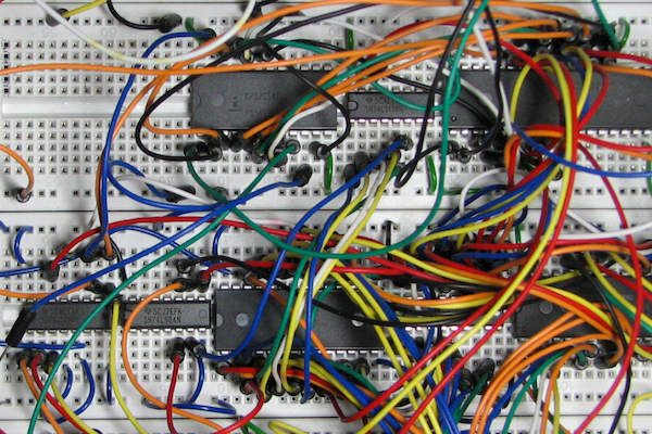
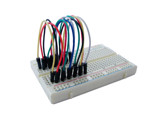
Two common styles are flexible leads with fitted connectors and low-profile solid-wire jumpers bent to span a chosen distance. A mixed pack can be useful while a layout is changing; individual cut-to-length wires can make the settled layout easier to follow.
How Breadboard Jumper Wires Work
A solderless breadboard contains internal metal contacts. A jumper bridges a point on one connected strip to a point on another. The wire's endpoints determine which circuit nodes are joined.
Start with the breadboard's connection pattern. The two halves of a typical terminal area are separated by the center channel. Power rails can also be separated or split along their length. Row labels and colored rail markings help you locate a connection, but the internal contacts establish continuity.
SparkFun's breadboard guide illustrates terminal strips, rails and connections. Trace the intended start and finish of each jumper against the circuit drawing.
Male-to-Male, Male-to-Female and Female-to-Female
The connector names describe the two ends of a lead. A male end has an exposed pin. A female end has a socket that accepts a pin.
- Male-to-male: Pins at both ends. These can join two breadboard holes or connect a breadboard to a board with compatible female header sockets.
- Male-to-female: A pin at one end and a socket at the other. The pin can enter the breadboard while the socket connects to a compatible exposed header pin.
- Female-to-female: Sockets at both ends. These connect compatible exposed header pins on two boards or modules.
Look at the actual connector on each board before choosing the lead. A socket-ended wire and a socket header need a pin connection between them; two pin-ended parts likewise need a suitable mating connection. Header spacing and the connector's dimensions also matter.
Adafruit's wires and connections guide distinguishes wire construction, cable assemblies and end connectors. Those are separate attributes of a circuit-board jumper wire.
Pre-Made Leads and Solid-Core Hook-Up Wire
Flexible Leads with Fitted Ends
Pre-made leads arrive with their ends already prepared. They are convenient for connections that move between breadboard rows and board headers. The connector housing gives you something to hold when placing or removing the lead.
Adafruit's pre-made jumper-wire examples show different lengths and configurations. Choose a route that reaches both endpoints while leaving nearby component labels visible.
Solid-Core and Pre-Bent Jumpers
Solid-core hook-up wire can be cut and stripped to the required length. Pre-bent jumper kits provide prepared segments that lie close to the breadboard. Both styles can make short connections easier to trace by reducing loops above the components.
For example, Digilent's breadboard wire kit uses pre-stripped, low-profile segments in assorted lengths. That is a different arrangement from flexible leads that arch between header connectors.
How to Choose Breadboard Jumper Wires
Choose the connection first, then the wire style. These five checks make the choice more specific than a generic “jumper wire pack” label:
- End connectors: Identify whether each endpoint is a breadboard contact, a header pin or a header socket.
- Reach: Select enough length to follow the intended route without pulling the endpoints sideways. Shorter local links and longer board-to-board leads serve different layout needs.
- Contact fit: Check the breadboard's accepted wire or pin dimensions. Wire gauge describes the conductor; the shape of a fitted connector pin is another measurement.
- Circuit requirements: Compare the assembly's wire, connector and insulation specifications with the circuit's voltage and current. A conductor gauge alone does not establish the rating of every contact in the connection.
- Identification: Use a consistent color convention and record the endpoint labels. Color makes tracing easier; it does not change the electrical connection.
Solid 22 AWG wire is a common breadboarding choice. SparkFun's wire-thickness reference identifies 22 AWG as a size it commonly uses for prototyping. A pre-made lead can have a different conductor size and a separate breadboard-compatible end pin.
Length also varies by pack. As one manufacturer example, Arduino's dual-male jumper-wire pack lists 100 mm and 200 mm leads. Compare the actual contents with your layout rather than treating a pack's total piece count as the deciding specification.
A Simple Way to Plan a Jumper Connection
Suppose a module has an exposed header pin labeled SIGNAL and the matching connection belongs on a breadboard row. A female-to-male lead provides the socket for the module pin and the pin for the breadboard. Record the module pin label and the breadboard row, then trace that same connection on the schematic.
If the module instead has a female header, the connector combination changes. The circuit connection you need stays the same; the physical ends needed to make it are different.
For board-reference terminology, continue with the GPIO numbering reference. The monitoring and interfaces guide covers the Raspberry Pi and Victron interface equipment I used in the van.
Keeping Connections Easy to Check
Group unused leads by connector type and length. Keep pre-bent segments organized so you can find a span without reshaping every wire. When reviewing a prototype, compare each lead's endpoints with the drawing and look for bent pins, loose housings or damaged insulation.
Change one connection at a time and keep the drawing aligned with the layout. This makes a moved wire easier to trace than relying on the overall appearance of a bundle.
Breadboard Jumper Wire Questions
Can I use regular wire as a breadboard jumper?
Solid-core hook-up wire with prepared ends can make breadboard connections. Its diameter and stripped-end length need to match the breadboard contacts. Loose strands from an unfinished stranded end behave differently from a single solid pin.
Do jumper-wire colors have fixed meanings?
The insulation color is a visual identifier. A consistent project convention helps distinguish power, ground and signals, while the actual circuit role comes from the connected endpoints.
Which jumper wire connects a breadboard to header pins?
A male-to-female lead is the usual connector combination: its male pin enters the breadboard and its female socket accepts the compatible header pin.