Choosing a camper van water tank starts with more than the number of gallons. My water-system purchases included a long, shallow Class A Customs UM-2000 and a separate narrow tank recorded through Pelland. My early interior-preparation notes also put openings for three tanks ahead of the finished interior. Those records bring me back to a practical layout question: where does the complete tank arrangement fit, including everything attached to it?
Start With The Space Before Choosing The Capacity
I used SketchUp to plan my interior, and the water equipment belongs in that same space budget as the bed, cabinets and framing. A tank occupies a real three-dimensional envelope. Its capacity is useful information, but it does not tell me whether the body clears an obstruction, whether a hose can turn, or whether a connection will disappear behind a finished panel.
My first step would be to identify the actual available location. For an interior position, I would mark the floor boundary, surrounding furniture and height to the underside of the next surface. For a proposed underbody location, I would record the actual open space and nearby vehicle structure. These are separate surveys, even when a tank's marketing name suggests one of them.
I would keep three outlines in the working model. The first is the tank body. The second includes the connections, plumbing turns and retention arrangement. The third is the temporary space needed to reach or remove something. That third outline matters because maintenance happens after the furniture is complete, when the empty area beside the tank may have become a cabinet or storage bay.
The result is a placement decision that can be checked against the build. A location that accommodates only the bare tank is still an unfinished proposal. A location that accommodates the body, connected parts and access paths gives me a meaningful basis for comparing another shape. I would settle those differences before choosing a bigger capacity simply because the larger number looks attractive.
This guide develops that placement comparison. My water-system concept covers the separate idea of a framed compartment, a pan and transparent access doors. Here I am concentrating on the tank's shape and occupied space, so those original compartment notes remain useful without being repeated as a second whole-system design.
Keep My Purchase History Separate From The Comparison
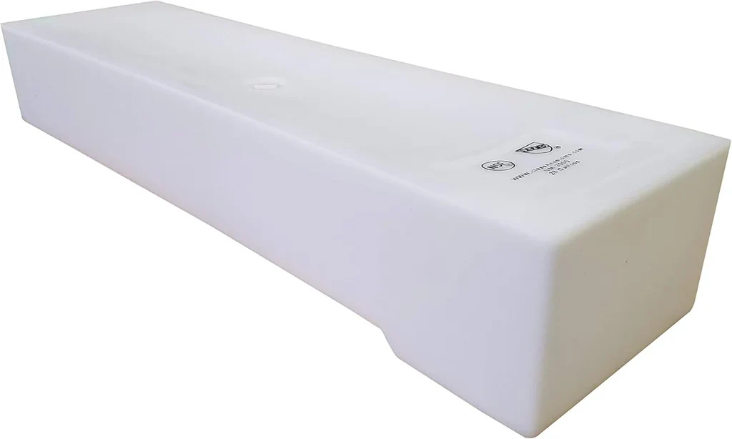
The UM-2000 is in my purchase records. Its long, shallow body makes it a useful starting point for discussing packaging. I also have a separate record for a narrow tank described as 53½ by 9 by 8 inches and 16.7 gallons through Pelland. I keep that purchase identity separate from the current rectangular Amazon option shown on its equipment page.
That distinction helps when returning to an older build. A current buying option can be useful to somebody planning a similar task, but it does not change the item in the original purchase history. In my notes, the narrow purchase remains the narrow purchase. The Class A Customs T-2000 and TORVA wheel-well tank are comparisons for different body shapes, rather than a rewritten account of what I bought.
I would use the same separation in a new build file. Give the purchase record its own name and keep the current candidate beside it. Add a status such as purchased, being compared or removed from the current plan. A component can remain in the history even when a different arrangement is being evaluated. That makes later photographs, drawings and orders easier to understand together.
My UM-2000 equipment page collects the model reference and comparisons. The narrow-tank purchase and current rectangular option page preserves the other distinction. I would open those records while drawing, then carry the exact selected model into the layout rather than relying on a generic water-tank block.
For the placement exercise, that leaves a clear starting point: my documented purchases explain why this subject belongs in my build planning, and the comparison shapes explain the choices a reader can evaluate. Each has a different job in the article and in the working file.
Compare Three Shapes At The Same Nominal Capacity
The useful comparison is not simply small tank versus large tank. The existing comparison set includes three twenty-gallon forms: a long, shallow under-mount style, a conventional rectangular body and a wheel-well form. Holding nominal capacity constant makes the packaging differences easier to see. The remaining question is which arrangement works with the space around it.
The UM-2000 spreads the volume along a long body. I would compare its longest edge with the uninterrupted space available, then examine the other two dimensions against the surrounding structure. That kind of shape can look compact from one viewpoint and demanding from another. A side view alone can hide the distance occupied along the van.
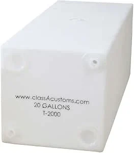
The rectangular T-2000 concentrates its volume in a different envelope. I would place it in the model as its own body, rather than scale the long tank until it appears to fit. A rectangular form changes what can sit beside it and above it. It also changes which faces are easy to reach once the surrounding cabinet is drawn.
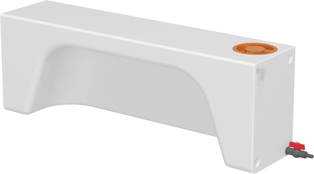
The TORVA comparison introduces a shaped recess around a wheel-well form. That is a different packaging idea again. I would compare the actual recess and the actual vehicle intrusion before assigning the neighboring storage space. A wheel-well shape in a product photograph is a reason to investigate the geometry, rather than a reason to skip measuring it.
This is why I would shortlist shapes before finalizing the compartment. Equal gallons can leave a long narrow remainder, a shorter rectangular remainder or storage divided around a shaped body. The useful winner is the arrangement that leaves the right space for the rest of the layout and the connected equipment, rather than the tank that looks smallest in a single photograph.
Treat Published Dimensions As A Body Reference
Class A Customs' tank dimensions chart separates measurements from fittings and lists a quarter-inch dimensional tolerance. It gives the UM-2000 a 48-inch edge with 8.5-inch and 13-inch edges, while the T-2000 is listed at 32.5 by 11.75 by 11.75 inches. Those figures describe different packages for the same listed twenty-gallon capacity.
I would carry that information into the drawing with the axes identified. A list of three numbers can be rearranged in conversation, but the model needs a consistent orientation and a clear reference face. Put the port face and the proposed viewing direction on the same working record. That prevents a dimension from being treated as height in one sketch and width in another.
Next I would model the connected envelope separately. A fitting extends beyond the tank body, and the hose or pipe attached to it needs a route. The amount depends on the actual connection selected. I would add those parts using their own dimensions instead of assigning a universal extra allowance to every side of every tank.
A physical comparison is useful here. Mark the proposed body boundary, then place representative connected parts in the direction they would actually run. Open the nearby door and follow the route back toward the next component. This makes the drawing easier to question because the tank, projecting connection and surrounding furniture are visible as separate things.
I would save the source document with that model revision. Later, when a cabinet dimension changes, I can see which tank record informed the drawing and which extra spaces came from my layout decisions. The layout measurement worksheet in Resources is a useful companion for organizing those measurements before they become a furniture cut list.
Compare Interior And Underbody Locations As Different Layouts
An interior tank uses space that might otherwise belong to furniture or storage. I would compare the complete cabinet arrangement with the tank present, including the door opening and the things stored nearby. A tank that fits beneath a surface can still make the space awkward if ordinary access requires unloading the adjacent compartment each time.
An underbody proposal changes the drawing rather than making the tank disappear from it. The body, its support arrangement and connected plumbing still occupy space. I would record the vehicle structures and other equipment around the proposed location and keep the actual mounting details with the tank selection. A product's under-mount name does not draw that vehicle-specific arrangement for me.
I would compare the two options with the same questions. Where does the fill connection begin? Where does the outlet travel? Which parts can be inspected directly? What has to move for removal? An inside-versus-outside decision becomes more useful when both proposals answer the same practical questions instead of one being detailed and the other being a blank area beneath the floor.
My early preparation notes are relevant because openings were part of the work being considered before the interior was enclosed. That sequence puts a decision in the right place: body access and component placement can affect later floor, wall and furniture work. I would keep the proposed opening location linked to the exact selected arrangement, so a later tank change also triggers a review of the drawing.
The comparison should finish with a complete candidate layout for each location. That includes the space gained, the space occupied elsewhere and the route between them. I would choose between those whole arrangements rather than describe an interior tank as automatically convenient or an exterior tank as automatically free space.
Give Connections Their Own Access Plan
I would begin the connection plan with the exact tank record, then identify the intended role of each opening in the selected arrangement. The fill, outlet, vent and drain routes do different jobs. Keeping them separate on the drawing helps me follow each path without assuming that every opening can be assigned interchangeably after the cabinet is finished.
The Class A Customs reference identifies its fresh/gray holding tanks as non-pressurized and describes venting during use. I would keep that source requirement with the chosen tank's documentation and give the corresponding route a visible place in the layout. A connection that is essential to the arrangement should not become an afterthought hidden behind a panel.
For each connected part, I would draw the direction in which it must be approached. There is a difference between seeing a fitting through an opening and being able to reach the connection behind it. The drawing should also show what has to be removed first. A direct route to one connection can become an indirect route once another component is installed beside it.
I would then run the same check with the neighboring storage in its ordinary state. If a compartment is intended to hold camping equipment, draw that occupied area too. An access opening that works only when the van is empty is a different arrangement from one that works with the everyday load in place. That distinction can change where I put the door or the stored items.
The point is to give every connection an understandable place and approach. A neat outline with all the plumbing omitted is easy to draw, but it leaves the decisions that determine the real compartment. I would rather resolve those decisions while the surrounding furniture is still a drawing than discover that the finished opening reaches the wrong face of the tank.
Draw Removal Space Before Closing The Furniture
My water-compartment concept included transparent doors because I wanted to be able to view the system. Visibility is one useful layer, and removal is another. A component may be visible through a large clear panel while still being trapped by a smaller frame opening. I would draw the route through the opening rather than assume that seeing the tank means it can come out.
Start with the largest item that would need to move. Show its path from the installed position to the accessible side of the compartment. Then consider what must be disconnected or temporarily removed along that path. The tank's orientation may change during removal, so the path is a sequence of positions rather than a single rectangle on the floor.
I would repeat that exercise for the connected parts that need their own access. Some may be reachable through a small opening while the main tank stays in place. Others may sit behind the tank and require a different sequence. Keeping those cases distinct helps me decide which panels should be removable and where a permanent divider would create extra work.
This also affects the neighboring furniture. A drawer, bed support or cabinet side can occupy the space needed only during removal. I would mark that temporary space in the model and decide how it is opened when needed. Otherwise it is easy to spend the same space twice: once for storage and again for a service route that no longer exists.
The useful check is to follow the complete sequence on the drawing. Open the door, reach the required connections, move the relevant parts and bring the component through the opening. If one stage remains undefined, I would keep the enclosure unfinished in the plan. That is a clearer next task than calling the tank placement complete because the body fits inside the cabinet.
Compare The Space Left For Everyday Storage
After placing each candidate tank, I would look at the remaining space as a storage layout in its own right. A thin gap beside a long tank is different from a shorter open bay beside a rectangular tank. Both may have measurable volume, but they will not accept the same objects or offer the same opening through the furniture.
I would assign a purpose to that remainder before treating it as useful storage. Draw the actual container or category of items intended for the space, then show how it comes out. A narrow vertical slot may suit one object and be awkward for another. This is the same reason a cabinet's outside dimensions do not tell the whole story about what it can hold.
Next I would check the boundary between stored items and the water connections. Give the plumbing its own route rather than making it share an undefined pile of equipment. That keeps the storage comparison consistent: the space counted for personal items should still be available when the complete connected arrangement is present in the drawing.
For an interior tank, the furniture surface above it also belongs in the comparison. It might be part of a seat, bed or counter arrangement. I would record which access task changes that everyday use and which can happen independently. A small maintenance opening and a removable furniture top create different routines, even when they enclose the same tank body.
I would finish this step by comparing complete neighboring spaces, not leftover cubic volume alone. What can be stored, how is it reached, and what happens when the tank needs attention? Those answers give the shape comparison a practical endpoint. They also make it easier to reject an arrangement that technically fits but leaves the surrounding furniture without a useful job.
Make One Decision Record For The Selected Arrangement
Once one candidate is ahead, I would put the decision on a single working page. Record the tank identity, the source drawing, the measured available space and the layout revision. Add the connection routes, access opening and removal sequence. This is a summary of the selected arrangement, with links back to the detailed records that explain it.
Keep the rejected alternative on that page with the concrete reason it lost. Perhaps the body occupied the required storage opening, or the connection face was difficult to reach in that location. A specific reason is useful if the surrounding design later changes. A vague note saying that another tank was better does not help me decide whether the original comparison still applies.
I would also identify the next physical check. That could be comparing an available component with the measured space, confirming a connected part's dimensions or checking the proposed furniture opening. Give the action an endpoint that can be recorded. The drawing becomes more dependable when open questions are converted into defined checks rather than quietly treated as settled facts.
My van-build decision log can keep that sequence alongside the rest of the project. If the tank changes, review the linked items together: the connected envelope, opening locations, cabinet boundaries and access path. A different body shape can affect several decisions even when the replacement has the same nominal capacity.
The final choice should explain what fits and why. It should also show the space that remains available for the rest of the van. That gives the next work session a concrete starting point and preserves the original purchase history, instead of allowing the newest product listing or drawing block to replace the record of how the layout developed.
One useful way to review the drawing is to walk through three different moments. First, imagine putting the empty component into the unfinished compartment. Second, look at the completed arrangement with its connected parts and ordinary storage present. Third, work backward through the removal sequence. These moments expose different boundaries, so I would give each its own check instead of marking the entire placement approved after the first successful fit.
I would photograph the physical comparison from the same direction as the drawing and save it beside the model revision. Include enough surrounding structure to explain the location. A close view of the tank alone can be useful for identifying a connection, but a wider view explains where the next cabinet edge or access opening belongs. The two views answer different questions and are easier to use when they stay linked to the same arrangement.
Finally, record which details remain unchanged when the drawing advances. If the tank and connection face stay the same while the cabinet door moves, carry those known parts forward and review the affected access path. That keeps a small furniture adjustment from turning into an unexplained whole-system revision. It also helps me return to the project later without having to reconstruct every earlier decision from scratch.
Frequently Asked Questions
Does Equal Capacity Mean Equal Installed Space?
No. The long shallow, rectangular and wheel-well forms in this comparison distribute their volume differently. Compare the body dimensions, connection locations and access paths together. I would also compare the usable storage left around each candidate, because a narrow remainder and a wide opening do different jobs even when both can be measured.
Is My Narrow Pelland Purchase The T-2000?
I keep those identities separate. My records describe a narrow Pelland purchase, while the T-2000 is the current rectangular option discussed on the related equipment page. The comparison is useful for understanding tank shapes; it does not change the item in the original purchase record or establish an installed replacement.
Should I Choose An Interior Or Underbody Tank First?
I would draw both complete arrangements before deciding. Include the tank body, connected parts, access and neighboring equipment for each location. Then compare the actual space and work involved in those two proposals. The useful choice follows the vehicle and furniture layout rather than a general rule about where every camper van should store water.
What Is The Best Next Step Before Ordering?
Measure the proposed space, select the exact model record and add the connected envelope to the drawing. Follow the inspection and removal paths with the surrounding furniture present. That produces a checkable placement proposal and a clear list of remaining actions, which is more useful than choosing a gallon figure and trying to fit everything around it afterward.
Compare The Catalog Options
Class A Customs UM-2000 — My Purchased Model
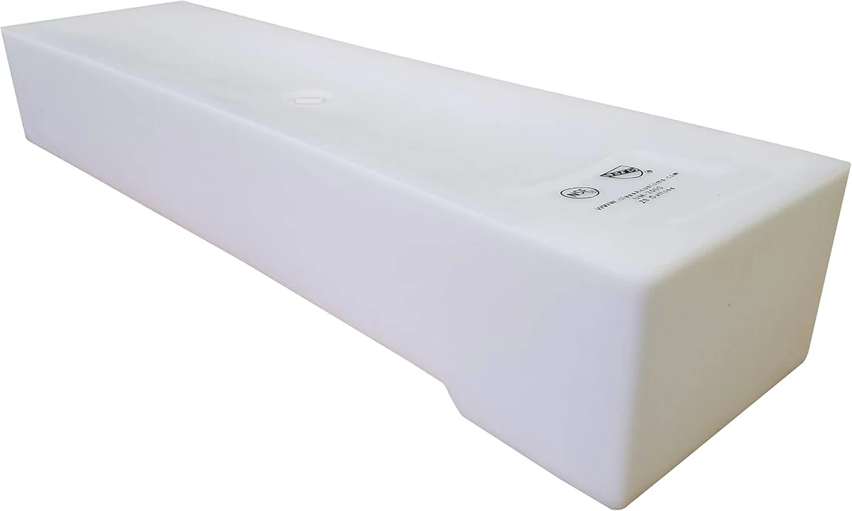
The UM-2000 is a twenty-gallon under-mount water holding tank. Its molded body provides connection points for a fresh- or gray-water layout.
View On AmazonClass A Customs T-2000 — Rectangular Alternative
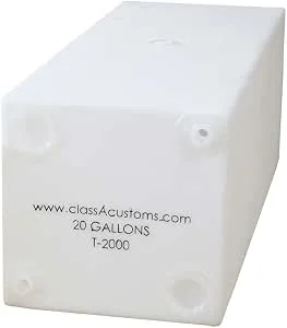
The T-2000 is a twenty-gallon water holding tank. Its rectangular molded body provides a different packaging shape from the under-mount model.
View On AmazonTORVA — Wheel-Well Alternative
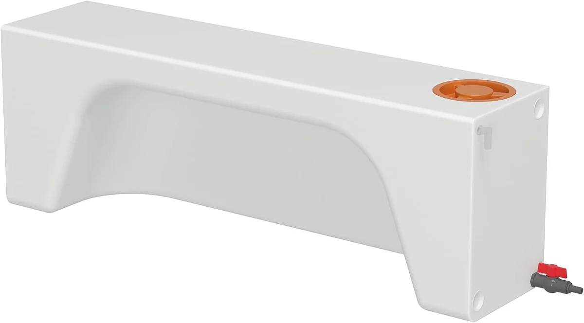
This twenty-gallon tank has a shaped recess for a wheel-well layout. Its molded body packages the water volume around that intrusion.
View On Amazon