A relay lets one circuit control switching in another circuit. For a camper van, identify the control input and the load separately before choosing a relay or module.
Separate The Coil From The Contacts
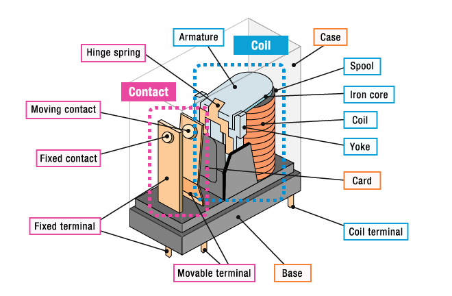
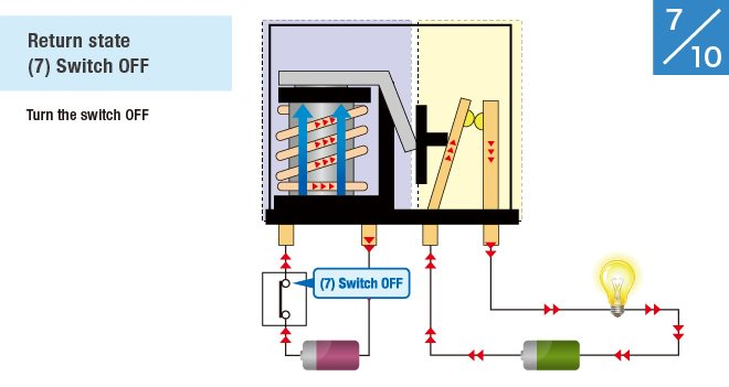
In a conventional non-latching electromagnetic relay, current through the coil moves an armature that operates the contacts. Normally open (NO) contacts are open with the coil de-energized; normally closed (NC) contacts are closed in that state. Latching types retain a state and need their own operating instructions.
OMRON’s relay introduction explains the mechanical action and distinguishes mechanical and solid-state types. Trace both circuits on the exact device drawing: how the coil receives power, and how the contacts connect the load. The load receives energy from its supply; the relay does not generate extra power.
Match The Load And Control Ratings
Check coil voltage and drive requirements separately from contact voltage, AC/DC switching capacity and load type. A resistive-load rating is not automatically a motor, pump or lamp rating. Startup current and switching conditions affect contact wear and service life.
OMRON’s general-purpose relay precautions cover load-dependent ratings and the voltage transient produced when a coil is switched off. Follow the selected device’s suppression and polarity instructions; suppression can change release time. Confirm whether a module includes a suitable driver and suppressor rather than assuming its input can drive a bare coil.
Check Solid-State Switching Separately
A solid-state relay uses semiconductor switching rather than moving contacts. That does not make every SSR interchangeable with a mechanical relay or automatically more reliable in a van.
OMRON’s SSR precautions describe output leakage, heat-dissipation requirements and short-circuit failure. Check the exact output’s AC/DC suitability, input requirements, mounting and thermal limits. An “off” command is not proof of an isolated or de-energized load. Plan the required means of disconnecting power independently of normal control.
Read The Existing Illustrations
Relay Parts And Moving Contacts
Coil-Off Return State
Record The Actual Circuit Before Wiring
For each proposed relay, record its model, control supply, load supply, NO/NC behavior, running and startup load, suppression arrangement and documented mounting limits. Add cable protection, terminals, access and the intended power-off behavior to the circuit drawing. Mark missing specifications as unresolved.
Continue with the wiring-diagram reference, the breaker comparison and the maintenance-access guide.