A transistor is a semiconductor device that controls electrical current and is used for switching or amplification. A signal applied to its control terminal changes conduction through another path in the device. This lets a circuit use a small control signal to manage a different signal or load current.
To read a transistor circuit, identify the transistor family, its terminal names and the role it performs. The same broad component family can appear in an audio amplifier, a digital logic circuit or a power-control stage.
How Does a Transistor Work?
A transistor changes its electrical behavior in response to an input. The input can move it between low-conduction and high-conduction states, or vary its output continuously through an operating range.
The transistor controls energy supplied by the circuit's power source. In an amplifier, for example, an input waveform controls changes in the output. In a switch, the circuit drives the transistor toward an off or on state.
Toshiba's transistor introduction explains the main device families, their terminals and their operating principles.
Transistor Types and Their Terminals
Bipolar Junction Transistors: NPN and PNP
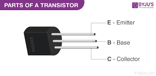
A bipolar junction transistor, or BJT, has three terminals:
- Base (B): The control connection.
- Collector (C): One terminal of the controlled current path.
- Emitter (E): The other terminal of that path and the reference for base-emitter bias.
NPN and PNP devices use different semiconductor arrangements and opposite bias polarities in their usual operation. In the active region, base current is related to collector current through the transistor's current gain. The relationship changes with operating conditions.
Toshiba's BJT reference distinguishes active-region amplification from cut-off and saturation used in switching.
Field-Effect Transistors: MOSFETs and JFETs
A field-effect transistor, or FET, uses a gate voltage to control its channel. Its principal terminal names are gate (G), drain (D) and source (S). The relevant control voltage is measured between gate and source.
MOSFET stands for metal-oxide-semiconductor field-effect transistor. Its gate is insulated from the channel. A discrete MOSFET commonly connects its body terminal internally to the source. JFETs use a junction-based gate structure.
MOSFETs include N-channel and P-channel devices, as well as enhancement and depletion types. An enhancement device is normally off at zero gate-to-source voltage; a depletion device is normally on. Toshiba's MOSFET guide explains these distinctions.
Insulated-Gate Bipolar Transistors
An IGBT combines an insulated-gate input with bipolar conduction characteristics. Its terminals are gate, collector and emitter. It is another transistor family used in power electronics, with different operating characteristics from a BJT or MOSFET.
Understanding Transistor Schematic Symbols
Start with the terminal labels. A BJT symbol identifies the base, collector and emitter, with an arrow on the emitter branch. The NPN arrow points outward from the base region; the PNP arrow points inward toward it.
FET symbols identify a gate and the drain-source path. Details differ between MOSFET and JFET symbols, channel types and operating modes. Toshiba's transistor classification and symbol examples provide a useful comparison.
The symbol shows electrical relationships. A physical package drawing shows which numbered lead or pad connects to each terminal. Rotating a schematic symbol does not change a transistor's terminal identity.
Transistors in Amplifiers
A transistor amplifier uses a changing input to control a corresponding output change. Depending on the circuit, the useful gain can be voltage, current or power gain.
The bias establishes the operating point. A small signal then varies the transistor's conduction around that point. In a BJT amplifier, the active region supports this relationship. The surrounding resistors, load and other components help determine the finished circuit's behavior.
Audio and radio circuits use amplification to work with signals that would otherwise be too small for the next stage. Imec's transistor explanation connects amplification and switching to their wider role in electronics.
Transistors Used as Switches
Switching circuits use a transistor to control whether a current path conducts. BJT switching commonly uses cut-off for the off state and saturation for the on state. An operating transistor still has electrical losses; the on state is different from a perfect connection.
For MOSFETs, gate-to-source voltage controls channel conduction. The insulated gate has very low steady-state input current, while changing its voltage involves charging or discharging capacitance.
Threshold Voltage Is Different from an On-State Specification
A MOSFET's threshold voltage is measured at a specified drain current. Reaching that threshold does not establish low on-resistance at the intended load current. Read the on-resistance specification alongside its stated gate voltage and test conditions.
Toshiba's threshold-voltage reference shows the specified-current measurement behind the threshold value.
Reading a Transistor Part Number and Datasheet
Use the exact manufacturer, part number and package when identifying a device. For example, the Renesas 2N3904 datasheet labels its illustrated package pins as 1 emitter, 2 base and 3 collector. Match those numbers to the package view shown in that document.
The same datasheet separates maximum ratings from electrical characteristics. Useful fields include:
- Voltage and current ratings: Limits for the specified terminals and conditions.
- BJT current gain: A value or range stated at particular collector-current and voltage conditions.
- On-state behavior: Saturation voltage for a BJT or on-resistance for a MOSFET, with the associated drive conditions.
- Power and temperature: Dissipation limits and thermal information for the package and mounting conditions.
A package shape alone does not establish its pin assignment or ratings. Keep the terminal diagram and test conditions with the part identity.
Where Transistors Are Used
Transistors perform several distinct jobs in electronic systems:
- Signal amplification: Audio stages, radio circuits and sensor-signal conditioning.
- Electronic switching: Load-control and power-management circuits.
- Digital logic: Networks of transistors form logic gates used in processors and other integrated circuits.
- Power conversion: Switching devices control energy transfer in converter circuits.
For related component terminology, continue with the diode reference and printed circuit board guide. My monitoring and interfaces guide identifies the Raspberry Pi and Victron interface equipment I used in the van.
Transistor Questions
Is a MOSFET a transistor?
Yes. A MOSFET is a type of field-effect transistor. “Transistor” is the broader category.
Can the same transistor be used for switching and amplification?
Some devices support both applications. The circuit's bias, operating region and component specifications determine how a particular device is used.
Does a transistor generate the extra energy in an amplified signal?
The circuit's power supply provides the output energy. The transistor lets the input signal control how that energy appears at the output.