These two archived illustrations show parallel solar-panel arrangements in different contexts. The first places a two-panel array inside a van charging-system overview. The second concentrates on a four-panel array and its connection to a charge controller. “Parallel” describes the solar grouping here; it does not describe every circuit in the complete van.
Identify The Two Examples
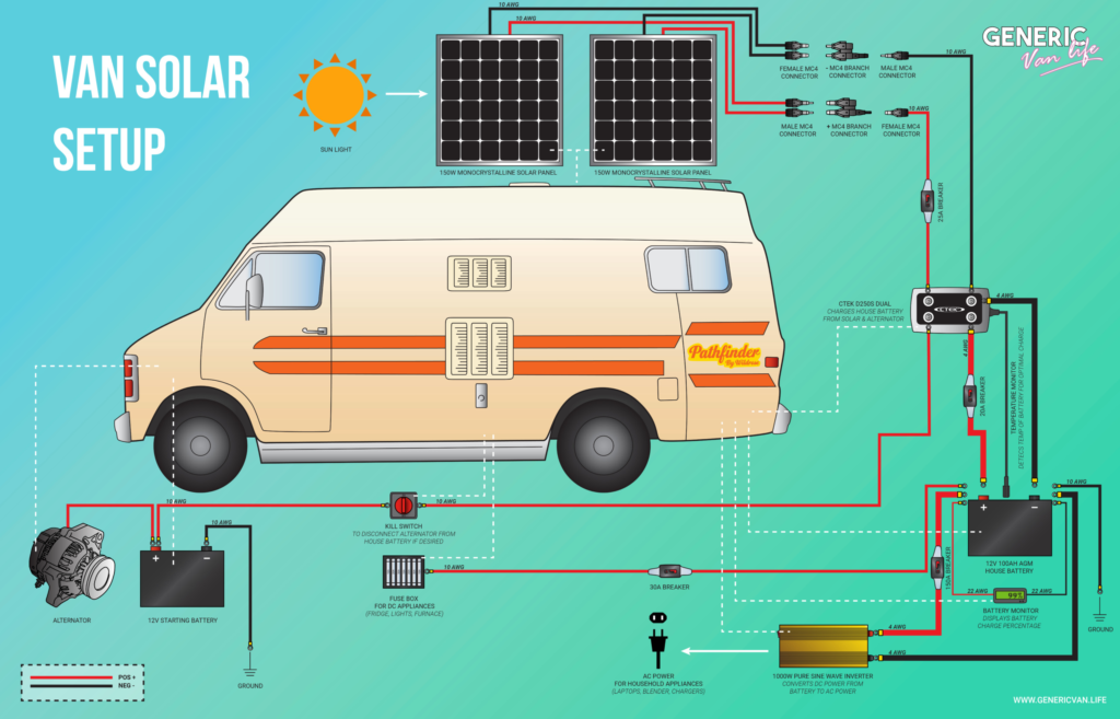
- Generic Van Life overview: the upper drawing shows two roof panels, a combined solar/alternator charging unit, a house battery, a DC fuse box and an inverter. It is a broad system illustration rather than a detailed drawing of every component.
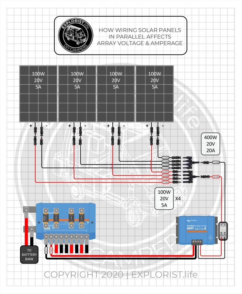
- EXPLORIST.life array example: the lower drawing is headed “How Wiring Solar Panels in Parallel Affects Array Voltage & Amperage.” Four panels carry example labels of 100W, 20V and 5A; the combined array is labelled 400W, 20V and 20A.
Read The Scope Before The Labels
Use the first image to identify the illustrated energy sources and destinations. Use the second to locate the individual panel branches and the shared output path. Keep the source name with each drawing when discussing it; the hardware pictured in one example is not a continuation of the other example.
The numeric labels belong to the archived examples. Keep the original component manuals and exact panel datasheets with any proposed design instead of copying a cable or protection label into a new equipment list.
Compare The Solar References
The parallel-panel reference explains a simpler three-branch drawing. The series reference and 2S2P reference provide contrasting arrangements. Record the chosen drawing, equipment models and unresolved questions in the decision log.
For the four panels and controller I installed, see my roof-solar setup.
Reference guide expanded October 20, 2026. Original publication date and archived references retained.