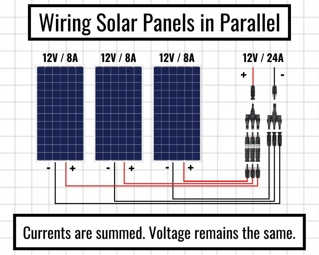
Parallel wiring joins like-polarity panel outputs into common positive and negative paths. The archived illustration below shows three panel branches joining at the right side of the drawing. It is useful for recognising that arrangement before comparing it with a series string.
Read The Parallel Diagram
Each panel is labelled 12V / 8A, and the combined output is labelled 12V / 24A. The caption summarises the simplified relationship: branch currents add while voltage remains at the panel-voltage level. The red paths lead toward the positive output and the black paths toward the negative output.
Those labels describe the example.
Record The Branch Details
Keep a separate line for each branch in the design record: panel model, quantity, datasheet reference and proposed cable route. Then record the shared output path and the exact controller model. This makes it easier to see which information belongs to one panel and which belongs to the combined array.
A parallel layout changes the current carried by shared wiring compared with an individual branch. A complete design therefore needs equipment-specific checks for the combining method, conductor and connector ratings, isolation and overcurrent protection.
For the underlying series/parallel principles, see Victron Energy’s Wiring Unlimited: DC wiring. Check the instructions for the exact equipment being considered.
Compare The Arrangements
Compare the series diagram, parallel diagram and two-series, two-parallel diagram. Keep the selected drawing, panel datasheet and controller manual together in the van-build decision log.
Reference guide expanded October 20, 2026. Original publication date and archived references retained.