Black Horse Spartan 17FT20MA Grille Guard: My Ford Transit Install
I bought Black Horse Spartan 17FT20MA Grille Guard on Amazon for my Ford Transit. This project follows my actual preparation, installation details and recorded result.
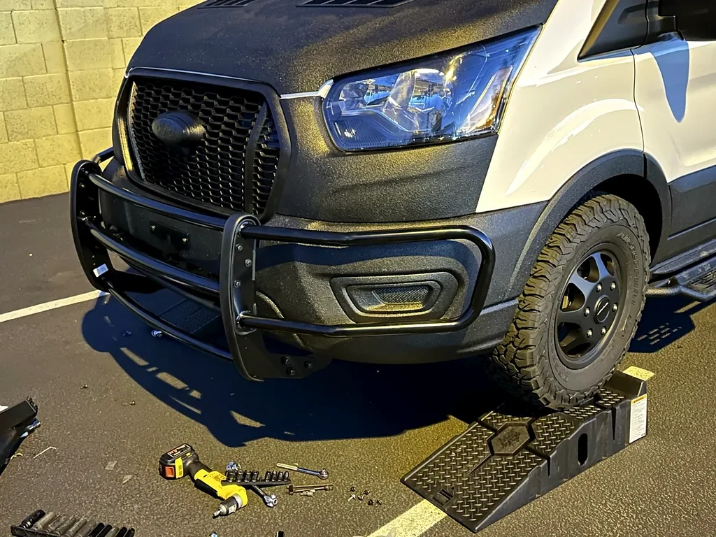
This project follows that sequence from the close-up work underneath to the finished appearance. The small connections explain the job better than a single photograph of the finished van: the splash-guard fasteners, the open license-plate position, the separate center support and the slotted mounting plates all appear in my original record.
Follow The Installation From Access To Finished Guard
The finished three-quarter photograph is the quickest way to see what I installed, but it is not the whole explanation of the job. The useful sequence begins underneath the front of the van, continues through the center mounting area and bracket alignment, and ends with the outer wings attached. Read those views in order to connect the visible guard with the work behind it.
The exact product in my purchase record is the Black Horse Spartan 17FT20MA. Keep that model identifier beside the installation photographs. The related guard options on this page have their own descriptions and vehicle applications; they are not all the same product because their frames look similar. The model and the actual vehicle configuration are the starting point for a fit comparison.
My written account, photographs and clips divide the work into several distinct stages. The splash-guard view explains access. The center-opening and support-bracket photographs identify the area being worked on. The center-section photograph shows the assembly before its final appearance. The completed views then connect those earlier parts to the guard visible across the front of the van.
For a reader planning the work, this sequence is useful as a project map. List the access, mounting, alignment and final assembly questions separately. That makes it easier to find the relevant photograph or clip when one particular part of the job needs attention, rather than repeatedly returning to a finished image that does not show the hidden connection.
Watch My Front Grille Guard Installation
Black Horse Spartan 17FT20MA Grille Guard: My Transit Installation — Landscape
Black Horse Spartan 17FT20MA Grille Guard: My Transit Installation — Portrait
The full film brings the preparation, exposed mounts, center support, alignment and finished photographs together in about two minutes and twenty seconds. The shorter videos below sit beside the parts of the job they explain, so it is easy to return to the splash-guard removal or the bracket connection without replaying the entire project.
| Stage of my project | What changed | Where to look |
|---|---|---|
| Access beneath the bumper | I removed the long black splash guard and recorded the clip problem. | Preparation clip and removed-panel photograph. |
| Mounting points and center support | The underbody mounts and the openings at the front license-plate position became visible. | Center-opening and loose-support photographs. |
| Bracket alignment | I left the connections loose while positioning the guard, then recorded tightening them. | Mounting clip and attached-bracket close-up. |
| Center section to finished guard | The three center rails were fitted before the outer headlamp wings appeared. | Center-only photograph, transformation clip and completed front view. |
Starting Underneath: Removing the Splash Guard
I began underneath the front of the Transit with a hand ratchet on the splash-guard fasteners. Some were already out when I recorded the first update, and I moved the camera along the underside to show the remaining ones. The bedliner on the fasteners made them harder to unscrew, so I was working them out manually.
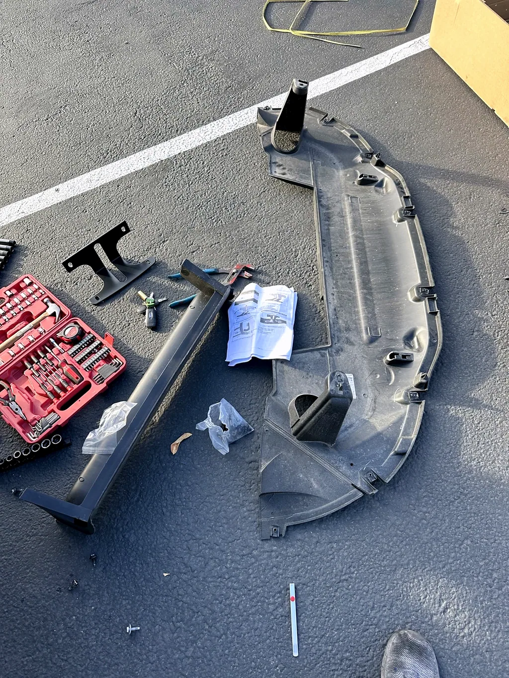
That part of the recording is close and practical. The front guard is the visible addition, but the first work was taking something off so I could reach the area behind it. Once removed, the long splash guard lay on the asphalt with its tabs visible. The parts and hardware were spread out nearby rather than hidden behind the finished assembly.
The Driver-Side Clip I Broke
I broke a small clip on the driver’s side during removal. In the next recording I tried to bring the corresponding area into focus on the passenger side and showed the clip where it entered the metal. I also pointed out the nearby bolt involved in getting the splash guard off.
The broken clip is part of this installation’s history. It belongs alongside the photographs of the finished guard because it explains what happened during access, before the new brackets were in position. My update records the problem at the time I encountered it, while I was trying to avoid repeating it on the other side.
What The Splash-Guard Removal Adds To The Story
The long black splash guard was an access step, not an unwanted leftover piece of the grille guard. My account shows its removal with a hand ratchet before the mounting areas became visible. Bedliner on the fasteners made that removal more difficult. This detail connects the new front-guard project with the exterior work already on the van without turning the page into a separate coating guide.
Keep fastener access and bracket access as different observations. First identify what must be reached to remove the covering panel. Then identify the mounting area exposed after it is out of the way. A finished front photograph cannot establish either of those steps. The underside clip is valuable because it shows the original working view that led to the later bracket photographs.
I broke a driver-side clip during removal and filmed the corresponding passenger-side clip and nearby bolt. The intact-side view helps explain what the broken part had looked like in position. It does not record a completed replacement or establish that the two sides have identical damage. Keep the broken-clip observation attached to its side of the van.
For a project record of your own, label the side and viewing direction before storing close photographs. A small clip or bolt can be difficult to locate later when the wider context is missing. Pairing an underneath view with a wider front view makes it easier to return to the same area after the larger guard is in place.
With the Splash Guard Off, the Mounts Were Exposed
My next update starts with the splash guard off. I showed the removed panel, then moved back under the van to the exposed brackets and bolts. I pointed to the locations on both sides where the new guard mounts were going to attach.
This is the transition between taking the existing panel off and building up the guard assembly. Looking underneath makes the relationship between the Transit’s structure and the new brackets easier to follow. The later close-ups show the bracket fasteners much more clearly, but this earlier view establishes where the work was taking place.
The mounting areas and the front-center support were separate parts of the same job. I recorded them separately too: first the access under the bumper, then the front license-plate area, and finally the attached bracket while I was tightening the assembly.
The Center Support Used the License-Plate Position
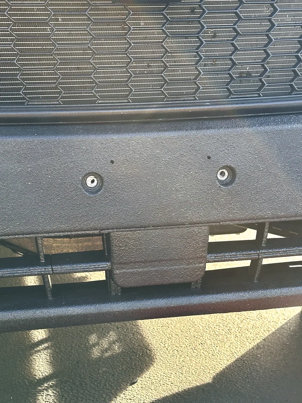
At the front of the van I showed the area where the license-plate bracket had been. Two larger threaded openings were exposed beneath the grille, with smaller holes nearby. In my recording I explained that the support bracket would go in that location to support the grille guard.
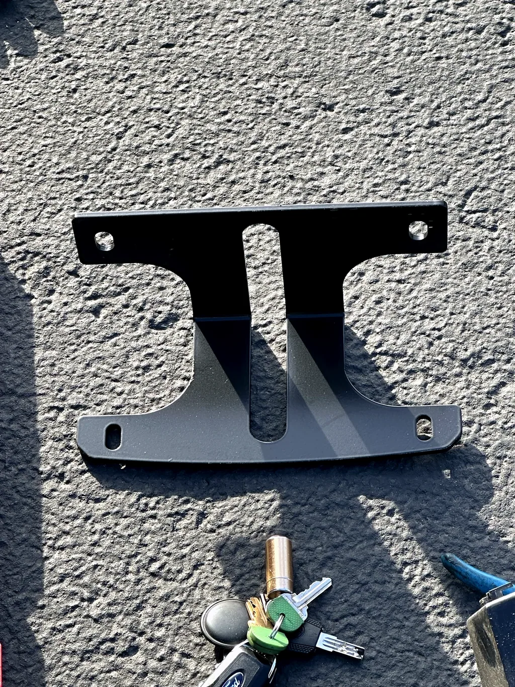
The separate support photograph gives a useful second view. On the ground, the black bracket’s bends, open center and different hole shapes are easier to see than they are once it is tucked into the assembly. Paired with the bumper photograph, it connects the loose part to the location I was discussing in the video.
Read The Center Mount And Loose Support Together
The center license-plate position is a useful landmark in the mounting photographs. The image shows two larger threaded openings and smaller holes in that area. Those visible openings explain where the account is focused, but a photograph of holes alone does not identify every supplied fastener or establish the specification for another Transit configuration.
The loose center-support bracket adds the next part of the explanation. Its bent shape and combination of round and slotted holes can be compared with the later attached view. Follow the same piece from its loose position to the mounted assembly. This is more informative than counting holes in isolation because the later view shows how the bracket was oriented in the actual project.
The attached-bracket photograph shows two upper bolts and three lower fasteners in the visible assembly. That is a description of the photograph, not a replacement hardware list. Keep the exact installation documentation and the supplied parts list beside the job when identifying what belongs at each position. The picture's role is to preserve my assembly stage.
A useful personal record can give each photograph a short location name, such as center support or front cross-section, followed by the side and stage. Retain the uncropped view as well as any detail. Later, if another front-end project requires access, those records can help identify which parts were exposed before the outer guard sections were fitted.
Leaving the Brackets Loose for Alignment, Then Tightening
By the next filmed update, the mounting brackets and grille guard were together. I was underneath again, showing the connection and explaining that I had left things loose initially so I could move them around. I then described tightening everything.
That is the clearest explanation I recorded of the alignment stage. The close-up photographs show the bent black bracket, two silver bolts at the upper connection and the fasteners across the lower guard-side plate. The slots are visible in those views, along with the guard tubing beside the plate.
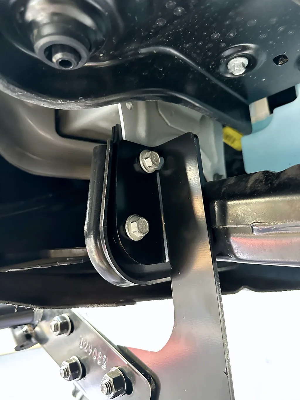
I find this close-up useful beside the wide front photographs. From a few steps away, the black bars dominate the view and the connection disappears into the underside of the van. Here, the plate, bolt heads and surrounding structure stay visible, tying my explanation about positioning and tightening to the actual assembly.
Why Alignment Appears Before The Finished Front View
My account describes leaving bracket connections loose while positioning the assembly and tightening them afterward. The important sequence is that positioning and tightening were separate activities. A photograph of the completed guard compresses those activities into one result, which can make the earlier adjustment work easy to overlook.
Look at the center-section photograph before the finished view with the headlamp wings. The center rails establish the middle of the guard. The outer sections change its overall width and appearance. Keeping those two stages in the record makes it clearer which part of the assembly was present when the positioning photographs were taken.
For a planning note, distinguish a visual alignment question from a fastener question. Visual alignment concerns where the assembly sits relative to the front of the van. A fastener question concerns the specific connection and its instructions. Writing down both prevents a satisfactory-looking front view from becoming the only record of how the work was completed.
The existing clip shows the support and alignment work from the project. Watch it with the bracket photograph nearby so that the close working view and the static assembly can be matched. Return to the exact guard's documentation for the installation values and hardware directions; this account does not add a torque number or a different tightening procedure to the photographed work.
The Center Section Came Before the Headlamp Wings
My photographs caught the guard with only its center section fitted. Three horizontal rails sat in front of the Transit’s bumper and grille, and the center support was visible at the license-plate position. The outer sections around the headlights were still absent.
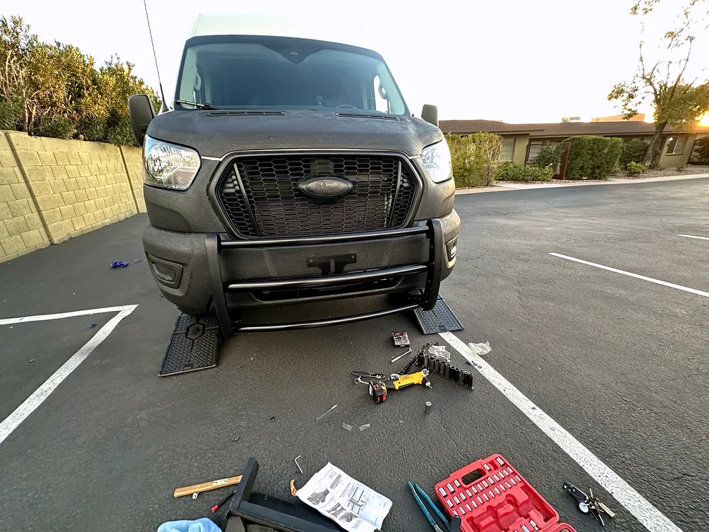
This intermediate photograph makes the progression clear. The center rails already change the outline across the lower front, while the headlamp areas remain open. In the completed photographs, the outer loops extend around those areas and join the center into a much wider shape.
The short transformation video is a sequence of my photographs. It moves from the center-only assembly to the completed guard and ends with the three-quarter view. The sequence lets the visual change speak for itself without adding narration to those still photographs.
The Completed Black Front Guard
The final front view shows both outer headlamp wings fitted with the center section. The black guard sits against the Transit’s black grille, textured hood and lower bumper, with the light-colored body around it. The three-quarter photograph at the start of this article shows how the wings project around the headlamp areas and how the side plate meets the center assembly.
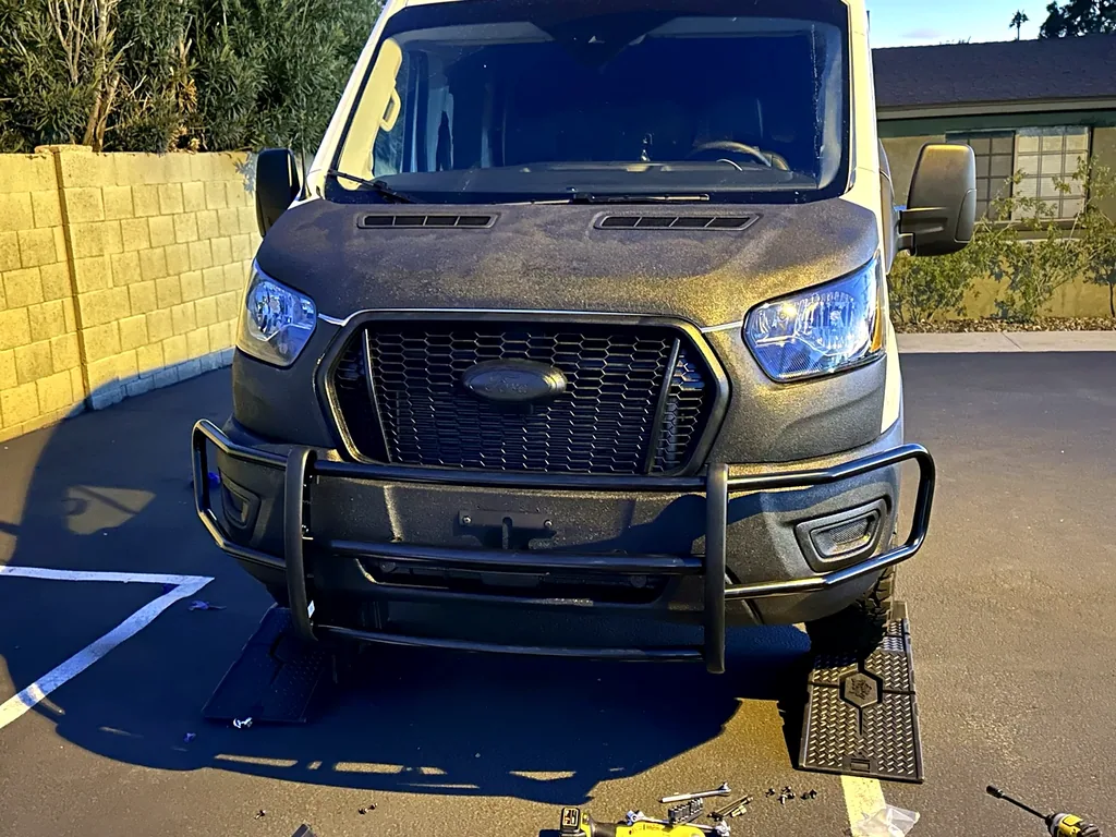
The most useful comparison in my project record is the center-only stage against this completed view. It shows exactly what the outer sections added to the appearance. The mounting photographs tell the other half of the story: the visible result came after removing the splash guard, working through the clip issue, positioning the support and aligning the bracket connections.
Compare The Three-Quarter And Straight-On Views
The driver-front three-quarter view shows the guard in relation to the side of my Transit and its black lower exterior. It is useful for understanding how far the front assembly visually projects and how the headlamp wings shape the overall appearance. The straight-on completed photograph answers a different question by showing the center rails and both sides together.
Use both views when evaluating the appearance rather than treating one camera angle as a dimension drawing. Perspective changes how much of a side section is visible. A close image may emphasize one wing, while a wider image makes the same guard seem smaller relative to the van. These are viewing differences, not measurements of another model's fit.
The earlier center-section picture is also worth retaining after the completed photograph is available. It records the part of the sequence before the outer sections finished the profile. If the final image alone were kept, the relationship between the three horizontal center rails and the later winged assembly would be much harder to follow.
For your own comparison, keep notes on the actual front-end details you need to access after installation. Identify those locations on your vehicle and compare the exact product drawings or instructions. The photographs here help explain the arrangement I installed; they do not supply dimensions for an unseen guard or demonstrate a different vehicle's clearances.
Use The Full Film And Short Clips For Different Questions
The full installation film provides the connected story of the work, while the shorter clips are useful for returning to a specific stage. Begin with the full sequence if you are unfamiliar with the project. Then use the splash-guard clip for the underside access and clip detail, and the support-and-alignment clip for the center bracket work.
A short transformation sequence is best read as an overview of changing appearance. It does not replace the slower working views or the written explanation of the broken clip. Keeping all three forms of material on the page gives a reader a choice between orientation, close detail and a quick reminder of the result.
When taking notes from a film, record the stage as well as the time. A note that says center bracket before tightening remains meaningful even if the video is later edited or a different clip is opened. A time stamp without a description is harder to connect to the static photographs or the installation documents.
The written captions remain useful when watching on a phone, where a small bolt or bracket may occupy only a few pixels. Open the relevant still photograph to study the location, then return to the film for the sequence of movement. That combines the strengths of the media without assuming that every detail can be identified from a quick mobile playback.
Keep The Original Guard And Comparison Options Distinct
The product box for my Spartan 17FT20MA preserves the guard associated with this installation. The alternative Spartan package with lights and the early-Transit TAC guard are different offers. Their pictures, descriptions and application details belong to those individual destinations. An alternative is something to compare, not a claim that I fitted every guard shown on the page.
Start a comparison with the actual van's front-end configuration, then identify the exact guard model and the relevant instructions. Keep any supplied lights or additional hardware in the complete package comparison. A photograph of my unlit assembly does not answer which lamps or mounting pieces arrive with another package.
The surrounding black exterior work also remains a separate project. It explains the appearance of my van and the coating on some fasteners during removal, but it does not change the guard's model identity. Use the linked exterior-coating account for that preparation and finish history rather than folding a second product review into the mounting instructions.
The completed record is therefore specific: the original guard purchase, the access work, the visible bracket stages and the final arrangement on my Transit. Those details make the page useful to revisit later and provide a clear comparison point without replacing the product-specific documents for another installation.
Follow the Rest of My Transit Exterior Work
The coated hood and lower panels visible here are part of my U-POL RAPTOR Black Urethane Bedliner Kit Project. That story follows the preparation, spraying, uneven sheen and roller correction behind that finish.
My Method Race Wheels MR701 Project follows another visible change to the van, from the original wheels at the shop to the installed result. For the work along the side of the Transit, read my HD Ridez N-Series Running Boards Project.
You can also browse my build diary by project to follow the individual jobs through my original photographs and notes.
The Product I Bought
This is the product behind my recorded project. The original photographs, video and installation details below show its role in my build.
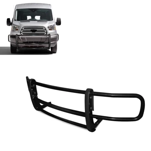
Black Horse Spartan 17FT20MA Grille Guard
The Spartan guard uses black metal uprights and crossbars across the front of the van. This modular model is listed for the later full-size Transit front-end design.
View On Amazon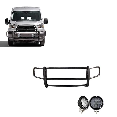
Black Horse Spartan Guard with Lights
This Spartan guard package adds a pair of lamps to its black modular frame. It is listed for the later full-size Transit front-end design.
Alternative To Compare
View On Amazon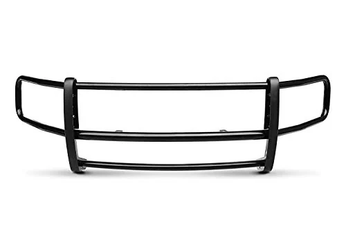
Tac Early-Transit Grille Guard
This black grille guard is listed for the 2015–2019 full-size Transit. Its uprights and crossbars form an external guard ahead of the front bodywork.
Alternative To Compare
View On AmazonFollow the Center Section Before Looking at the Wings
The center-only photographs are an important pause in my installation story. They show the main guard at the front of the van before the outer sections extend around the headlamp areas. Comparing that intermediate stage with the completed three-quarter view explains the change more clearly than jumping straight from loose brackets to a final photograph. The full film, stage clips and photographs on this page remain together for that reason.
Explore My Front Grille Guard Video Collection for the films, stage clips and viewing guide.
Questions from This Project
What Happened During Splash-Guard Removal?
My preparation recording includes the splash-guard work and the broken driver-side clip. I then show the mounting area exposed beneath the front.
Why Show The Guard Before The Headlamp Wings?
That intermediate photograph records the center section before the outer pieces. It makes the assembly sequence and the completed appearance easier to compare.
Does The Transformation Clip Contain A Spoken Installation Explanation?
The transformation clip is a photographic sequence. The preparation and mounting clips contain the recorded process context, and the written project story connects the stages.