Fitting My Roof Rack: Crossbeams, 2020 Rails and LED Mounts
during the Roof Wiring and Devices Project Day 1 session, I moved my Flatline roof-rack crossbeams to suit the solar-panel length, added 2020 extrusion above the rack and made aluminum plates for two small LED lights. The useful story is in the fitting sequence: an existing rack, another layer of rails, panels brought up for a trial fit and small mounts made to lift the lights.
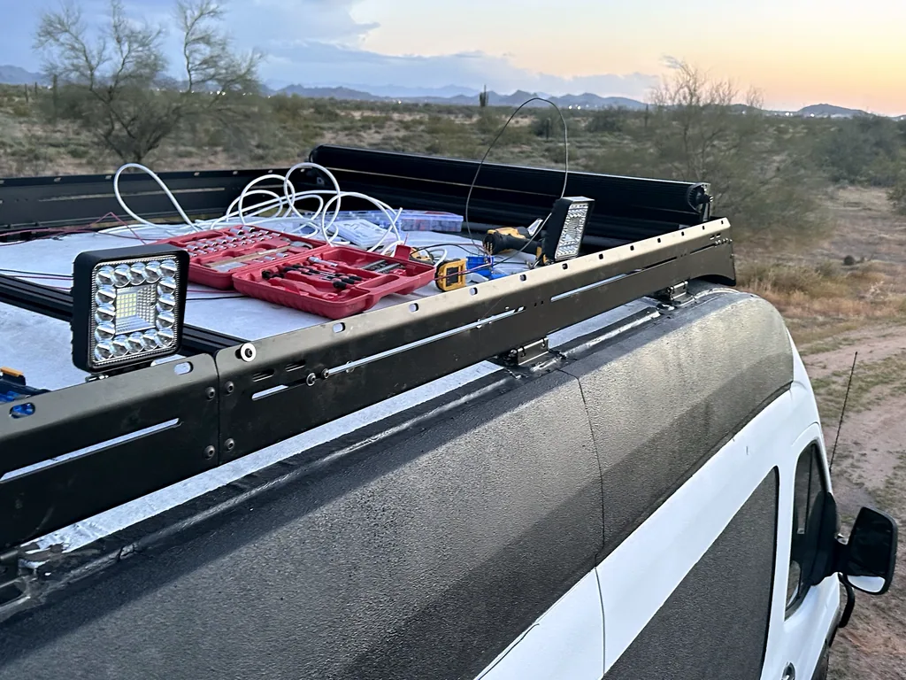
The Roof Wiring and Devices Project Day 1 records a 12-hour session that also included junction boxes, conduit and wiring work. The overall roof project was still in progress. These photographs show the mechanical arrangement during that session, with tools, leads and other work still on the roof.
Watch My Roof Rack Fitting Film
My narrated film follows the crossbeam adjustments, added 2020 extrusion, panel trial fitting and small-light mounting plates. This was a fitting stage on the existing rack, with the wider roof project still in progress.
Press Play To Start The Video.
Read The Video Transcript
Hi, I'm Steve Smith with Camper Van Freedom. My roof-rack fitting sequence started with a rack already on the van. I moved its crossbeams, added another layer of extrusion, brought two solar panels up for fitting and made plates for the small lights. These steps were part of a twelve-hour roof-work session that also included electrical tasks. The wider project was still in progress.
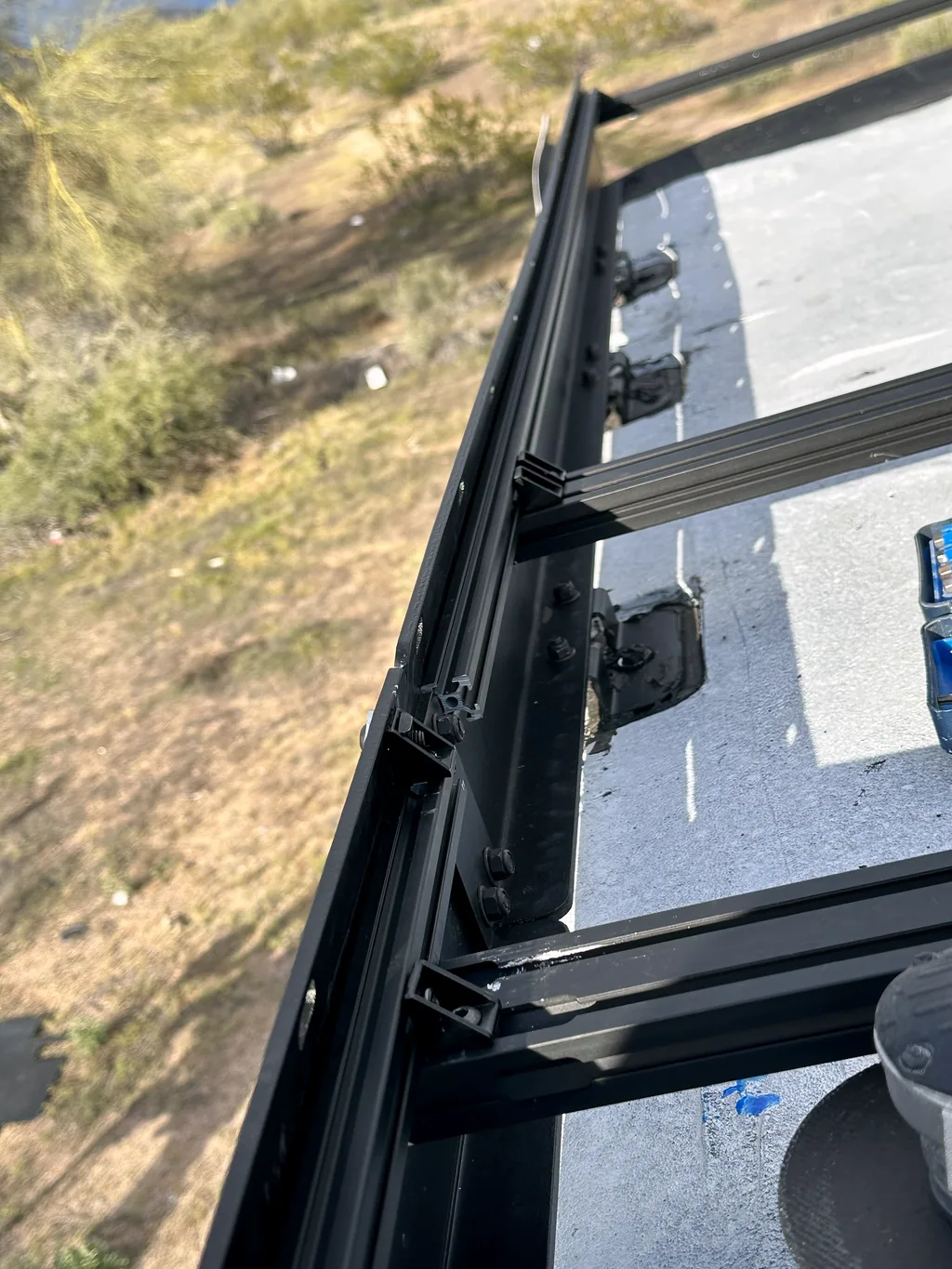
The existing rack was the starting point. The added twenty-twenty extrusion sat above the original rack extrusion, so those were separate layers of the arrangement. A lengthwise photograph shows their relationship across the roof. A close-up gives another kind of information: which corner bracket connects the pieces and where its fasteners sit.
My numbered diary steps put moving the crossbeams first. I moved them to suit the solar-panel length, then installed extrusion above the existing rack with corner brackets. The order matters because the new pieces were being fitted to an arrangement already in place. This was a sequence of changes to the rack, rather than a photograph of loose rails laid out independently.
I then brought two solar panels onto the roof for fitting. That trial position had its own place in the recorded sequence. The following step was cutting twenty-twenty extrusion to size. I keep the panel fitting separate from later electrical connections, because the diary describes what I was checking and fabricating during this particular stage of the build.
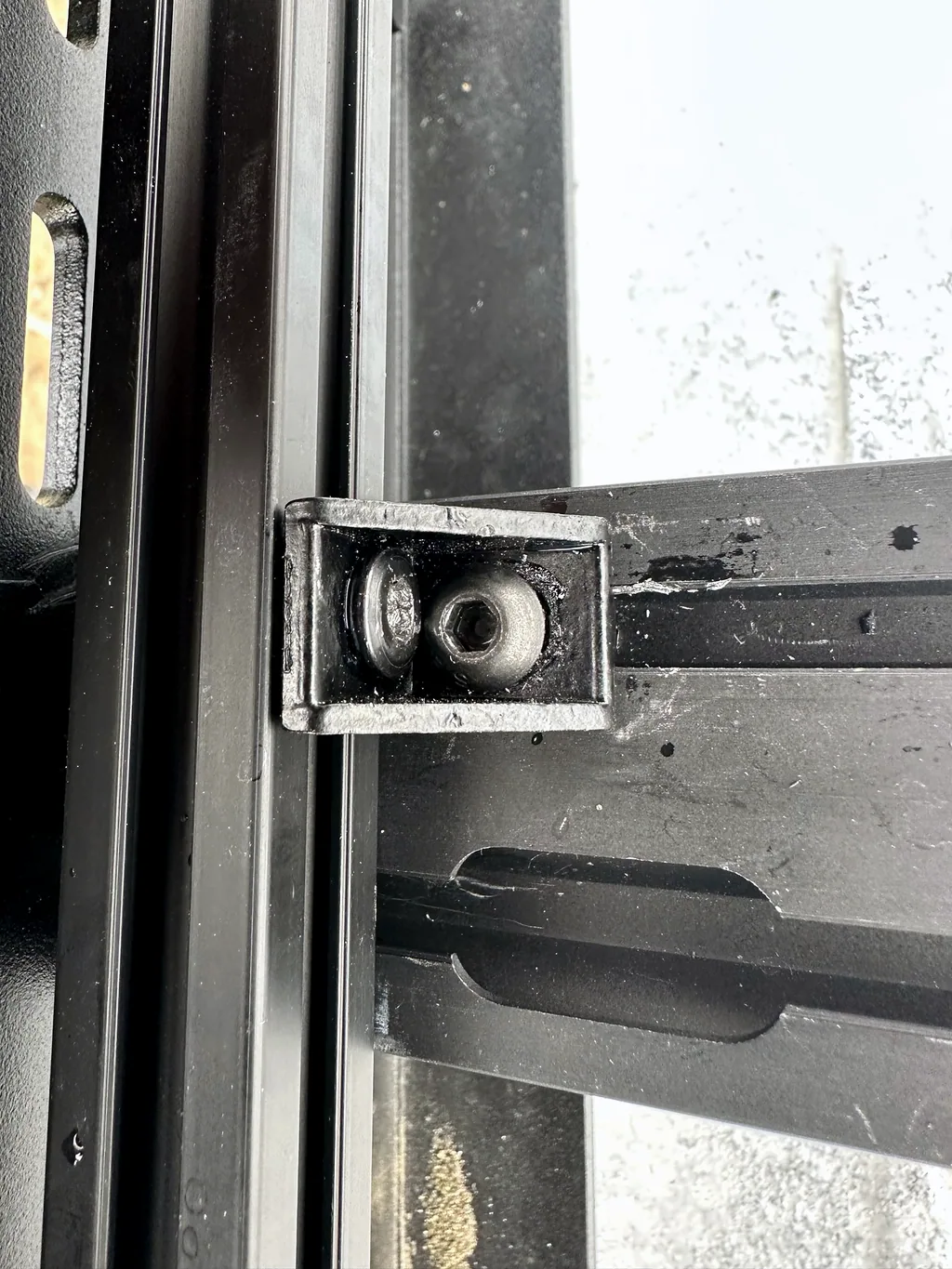
The corner connections joined the added extrusion to the rack below. One photograph shows a bracket with a fastener visible on each face. The wider view places that connection among the surrounding rails. Keeping those two views together helps locate a small joint later: one explains the connection itself, and the other explains where it belongs in the roof arrangement.
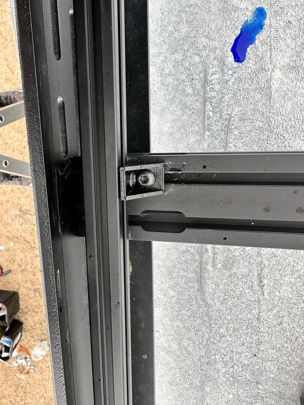
The small lights needed another fabrication task. I cut flat aluminum plates and drilled their holes, using two plates per light to lift the lights. I then mounted two small L E D lights along the passenger-side extrusion. The closer photograph shows the light's own mounting bracket, its side fasteners and the rail underneath. Those small pieces explain something a wide roof photograph cannot show on its own.
The same work area still held tools, loose leads, junction boxes and conduit. Those details belong to the stage the project had reached. The next session moved into the camera-bracket work, with more extrusion, drilled connections and small fastening pieces. The mechanical fitting, camera attachment and later cable route each had their own sequence within the wider roof project.
Thanks for watching. I'm Steve Smith with Camper Van Freedom. My roof-rack takeaway is the fitting order: move the crossbeams, add the rails, bring the panels up for a trial position and work through the light mounts. The full guide, original diary photographs and related roof-layout pages are linked below. Until next time.
Watch This Film On YouTube · English Captions (VTT) · Download The Transcript
The Flatline Rack Was My Starting Point
I was working on the Flatline Van Co Low Pro rack on my extended Transit. The Roof Wiring and Devices Project Day 1 changes involved its existing extrusion crossbeams and the additional 2020 extrusion I attached above them. The original rack and the added rails were separate parts of the arrangement.
That distinction is visible in the photographs. The wider rack structure remains underneath, while the added profile and its corner connection sit above it. A photograph of the whole roof gives the location; a close-up makes the joint understandable.
The Rack and Panel Fitting Sequence I Recorded
My numbered diary steps put the crossbeam move before the added extrusion and the two-panel trial fit. They then record cutting 2020 extrusion to size, followed by making the small-light plates and mounting the lights. The panel visit to the roof was explicitly for fitting.
| Diary Step | Work Recorded | Part Of The Arrangement |
|---|---|---|
| 7 | Move the Flatline crossbeams to fit the solar-panel length | Existing rack |
| 8 | Install 2020 extrusion above the existing rack extrusion with corner brackets | Added rails and their joints |
| 9 | Bring two solar panels onto the roof for fitting | Panel trial position |
| 10 | Cut 2020 extrusion to size | Extrusion fabrication |
| 11 | Cut and drill flat aluminum plates to lift the small lights, two plates per light | Light-mount pieces |
| 12 | Mount two small LED lights on the passenger-side 2020 extrusion | Light positions on the rail |
The 12-hour total belongs to the whole day's roof work, including the electrical tasks. The table isolates the mechanical entries so I can follow the crossbeams, rails, panels and light mounts through that larger session.
Adding 2020 Extrusion Above the Rack
I recorded using corner brackets to attach the 2020 extrusion on top of the existing Flatline rack extrusion. The close-up below shows the bracket at the connection, with a fastener visible on each face. The wider view places that same type of connection in the surrounding rails.
IXGNIJ 2020 extrusion appears in the materials for this work and in my purchase catalog. My materials also list an M5 T-nut and screw assortment. The diary supplies the actual use of the added profile; the close-ups preserve the connection I made.
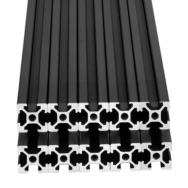
Ixgnij 2020 Aluminum Extrusion
These black aluminum profiles use a 2020 T-slot section. Their two-meter lengths provide rail stock for cutting and assembling modular structures.
View On AmazonKeeping both views together makes the connection easier to find again among the roof equipment. The close-up identifies the bracket and the fasteners. The wider photograph shows which rail and crossbeam meet there.
Making Plates to Lift the Small LED Lights
The small lights needed their own mounting pieces. I cut flat aluminum plates, drilled their holes and used two plates per light to lift the lights. I then mounted two small LED lights on the 2020 extrusion along the passenger side.
The light photograph shows the relationship between the light's own mounting bracket, its side fasteners and the rail below. My flat-bar stock record supplies the related material context. This was a separate fabrication task from moving the rack crossbeams.
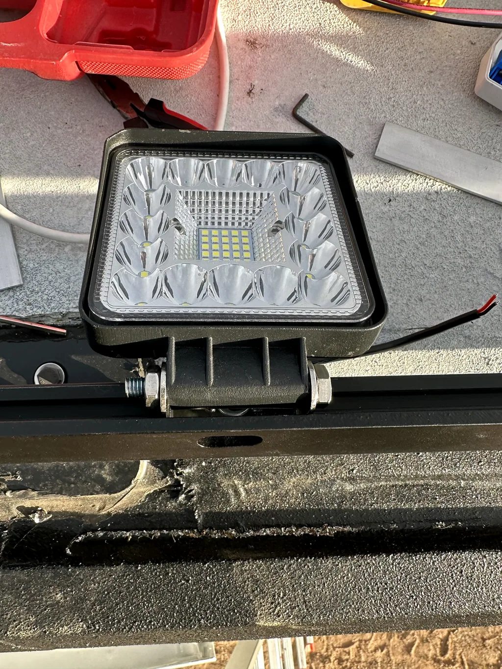
One reason this part of the photo record matters is its scale. A wide roof view shows where the light sits; this closer view shows how much of the job is in the small pieces underneath it. The two-plate count comes from my written steps, alongside the photograph of the assembly.
Where This Fitting Stage Led Next
My Roof Wiring and Devices Project Day 1 entry ended with more roof electrical work planned. The conduit, junction boxes and loose leads shared the same work area as the fitting changes. Keeping them in the wide photograph helps preserve the stage the project had reached.
The next session became the roof-camera bracket work on Days 96–97, with more extrusion, drilled brackets and small fastening pieces. That guide follows the camera attachment and the problems I recorded with T-nut positioning and bolt lengths.
My main takeaway from Roof Wiring and Devices Project Day 1 is the sequence of changes to an existing rack: move the crossbeams, add another profile, bring the panels up for fitting and work through the light mounts. For the broader equipment layout, my roof-vent planning guide puts the fan, panels, rack and cable routes on one plan. The roof-solar page follows the panels within the electrical system.